
Condition Evaluation of Fire Exposed Concrete Foundation
INTRODUCTION
After a devastating fire to a building, concrete and masonry members are most likely to be the only surviving structural members. Fire consumes wood rapidly and distorts exposed steel structures within minutes. Although steel structures regain strength upon cooling, it remains structurally distorted, which makes the strength gain useless. History has shown that concrete structures possess excellent fire resistance and can retain its structural integrity even in severe building fires. The cast-in-place reinforced concrete columns, slabs, and walls are likely to remain in place longer than their expected code compliant duration and thus provide occupants valuable time to escape the building. Wood and exposed steel frame structures do not offer this level of fire resistance and advantage. Concrete’s inherent low thermal conductivity and high specific heat allows it to provide good protection forreinforcing steel against fire, though it may sustain extensive damage in the process. Under certain conditions, however, concrete may suffer significant distress. One such condition is when fire is caused by long term burning due to a fuel source in direct contact with concrete. However, in contrast to other construction materials such as timber and steel, concrete’s superior fire resistance allows it to repair in-situ or with partial replacement as compared to complete demolition and reconstruction. However, thorough investigation and testing is required to assess the concrete’s structural damage to determine itscondition as well as that of the reinforcing steel before it is considered for repair or reuse. The objective of this paper is to provide some basic information on effects of fire on concrete, various condition evaluation methods, and show findings from a case study of a fire exposed concrete foundation in California.The other objective of this paper is to inform construction professionals that fire exposed concrete structures can be successfully repaired without destroying and re-building the structure.
EFFECTS OF FIRE ON CONCRETE
Reinforced concrete structural members can sustain various degrees of fire distress to both concrete and reinforcement components. The degree of distress depends on the temperature and duration of the fire. The type of aggregate in concrete also have a great influence on fire resistance. The type of concrete affects thermal diffusivity, conductivity, and coefficient of expansion of concrete. Light weight aggregates transmit heat slower than siliceous aggregates or imestones. Generally, siliceous aggregates show poor fire resistance as compared to lightweight and smaller aggregates. The resulting damage could be individual pop-outs to widespread spalling. Common changes in concrete properties associated with various fire temperatures are as follows:
- Up to 120°C (248°F): The free moisture is lost. No change in color. No significant change in the concrete properties.
- Up to 250°C (482 ºF °): Complete loss of free moisture. Dehydration begins. Reduction in paste volume and beginning of strength loss.
- 300°C to 600°C (572-1,112°F): Color change to Pink, some cracking in paste and aggregates.
- Greater than 600°C (1,112°F): Complete dehydration of cementitious paste, concrete becomes friable, loses strength and concrete color changes to grey.
- Greater than 900°C (1,652°F): Color changes to buff.
- 1400°C (2,552°F): Concrete may decompose.
The primary effect of fire on concrete are as follows:
- Color change
- Spalling
- Cracking
- Reduction in modulus of elasticity & compressive strength.
- Possible loss of bond between reinforcing steel and concrete.
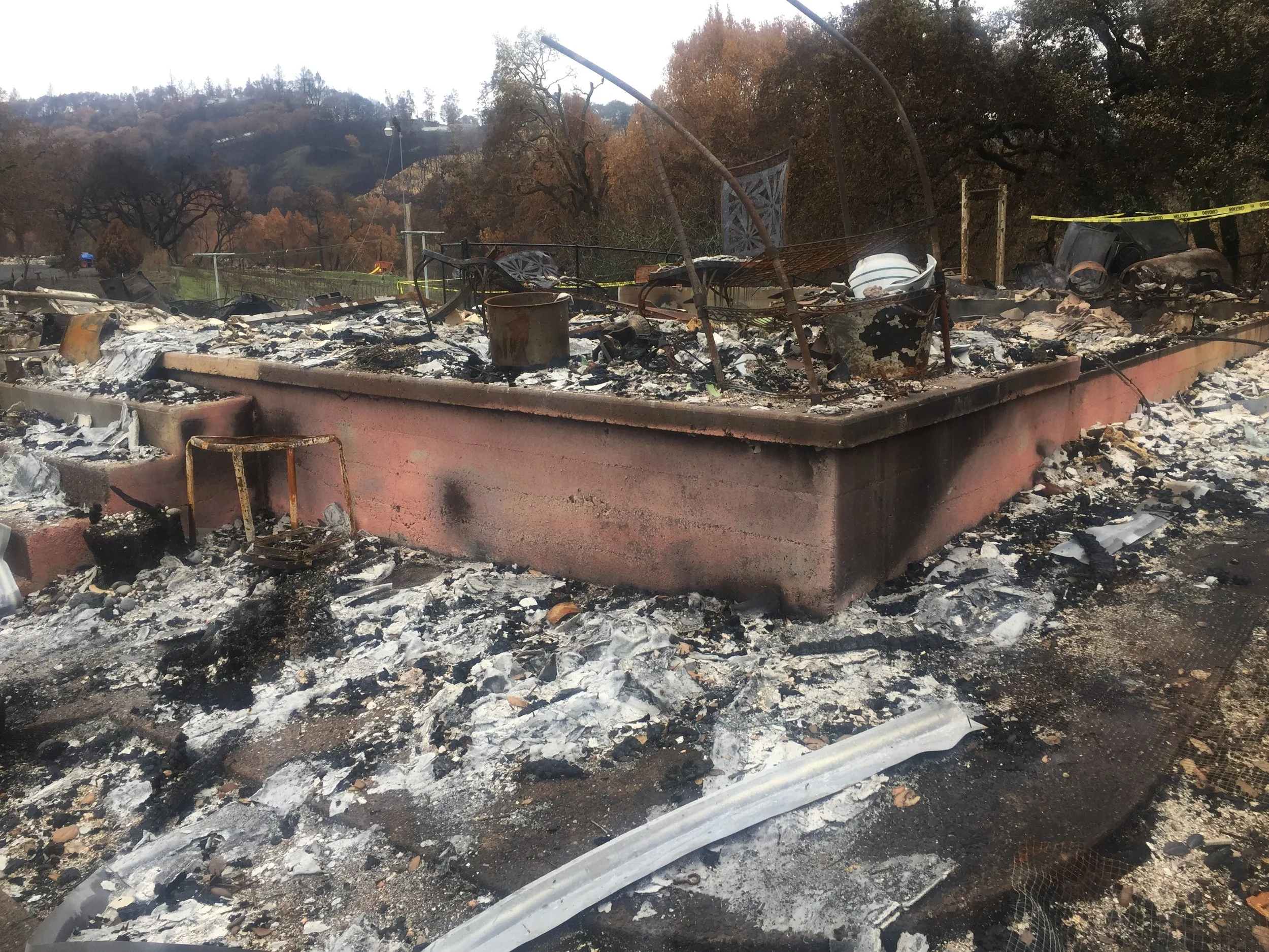
Photograph 2: The concrete foundation exposed to fire shows a pinkish color on the fire exposed side and its original grey on the interior fire exposed side. The corners show whitish-buff color.
Color Change
The pink discoloration, as seen in Photograph 2, indicates that the concrete surface has experienced a minimum temperature of 300°C (572°F). This discoloration can be associated with a loss of strength within the discolored concrete zone. If the pink zone has not reached the reinforcing steel or prestressing strands, then it is unlikely that the steel has been seriously affected by the fire exposure. The pink color occurs due to ferrous salts in cement paste, aggregate or sand. Concrete containing siliceous aggregates ismore likely to show pink discoloration than concrete that is made of calcareous or igneous aggregates.

Photograph 3: A close-up of whitish-buff colored concrete shows severity of damage to concrete, considerably weakening it.
In some cases, the color change is very subtle and may not show on the surface. In other cases, a whitish buff color concrete may be observed which indicates a higher temperature exposure. Photograph 3 shows the edge of a concrete foundation that demonstrates whitish-buff color, indicating that the concrete was essentially pulverized.
Spalling
Spalling of concrete,as seen in Photograph 4,is one of the most obvious visual signs of fire affected concrete. Typical concrete contains water in various forms such as free water, capillary water, and adsorbed water. The temperature of concrete does not rise until the evaporable water that is present is converted to steam. If this steam can escape the concrete, then it does not build up steam pressure in the pores of concrete. However, if the rate of evaporation is high and the permeability of the cement paste is low, then spalling can occur. Therefore, spalling is more noticeable in high strength low permeability concrete.

Photograph 4: Typical spalling of fire exposed high strength concrete surface.
Spalling of concrete may or may not represent a serious concern, but it provides useful information. If the spalling does not reach the reinforcement, and the structural member does not show signs of excessive deflection, buckling, or other distortion, then it is most likely that the reinforcing steel is unharmed. In heavily reinforced columns, however, it is possible for the reinforcing bars to reach 600°C (1,112 °F) without exhibiting severe distortion or buckling. Exposed steel in a column requires more detailed investigation. If quenching with water is used during the firefighting operation, then quenching of steel may result in loss of ductility. Spalling of concrete in prestressed concrete that exposes steel strands can be a serious concern. The strand exposed to fire may lose prestressing which may cause a reduction in the load carrying capacity. Therefore, spalling of concrete needs to be properly evaluated based on the type of concrete and its structural member.
Cracking
Cracking can occur either parallel to the surface or within the fire affected zone. It occurs where the heating and cooling of concrete during quenching has caused excessive tensile stresses. Cracking may look like drying shrinkage cracks andcan penetrate several inches into the concrete. Therefore, it is important that an experienced and licensed design professional is involved in condition evaluation of a fire exposed concrete structure.
CONDITION ASSESSMENT
The condition assessment of fire exposed concrete is generally done in two stages: 1) Preliminary site inspection, and 2) Detailed site inspection. The preliminary site inspection is generally qualitative in nature and its objective is to determine if the structure is salvageable and if a detailed investigation is warranted. The preliminary investigation can also determine if the structure can be repaired or requiresdemolition. Typical preliminary investigation consists of a site inspection performed by an experienced and licensed design engineer and may include: 1) visual inspection, 2) hammer sounding, 3) Nondestructive Rebound Hammer tests.
A follow-up detailed investigation should consist of some or all of the following tests:
- Visual survey to document degree of damage: locations of color change, spalling, & cracking.
- Rebound Hammer Survey to estimate residual compressive strength of concrete.
- Pulse Velocity or Impact Echo Tests to determine quality of concrete and locate any significant internal distress.
- Coring for concrete samples to determine residual strength of concrete.
- Reinforcing sample for yield strength test.
- Microscopic examination of concrete core to determine degree of fire damage.
- Pull test on steel anchors to determine bond strength between steel and concrete.
- Load testing to determine load carrying capacity.
CASE STUDY
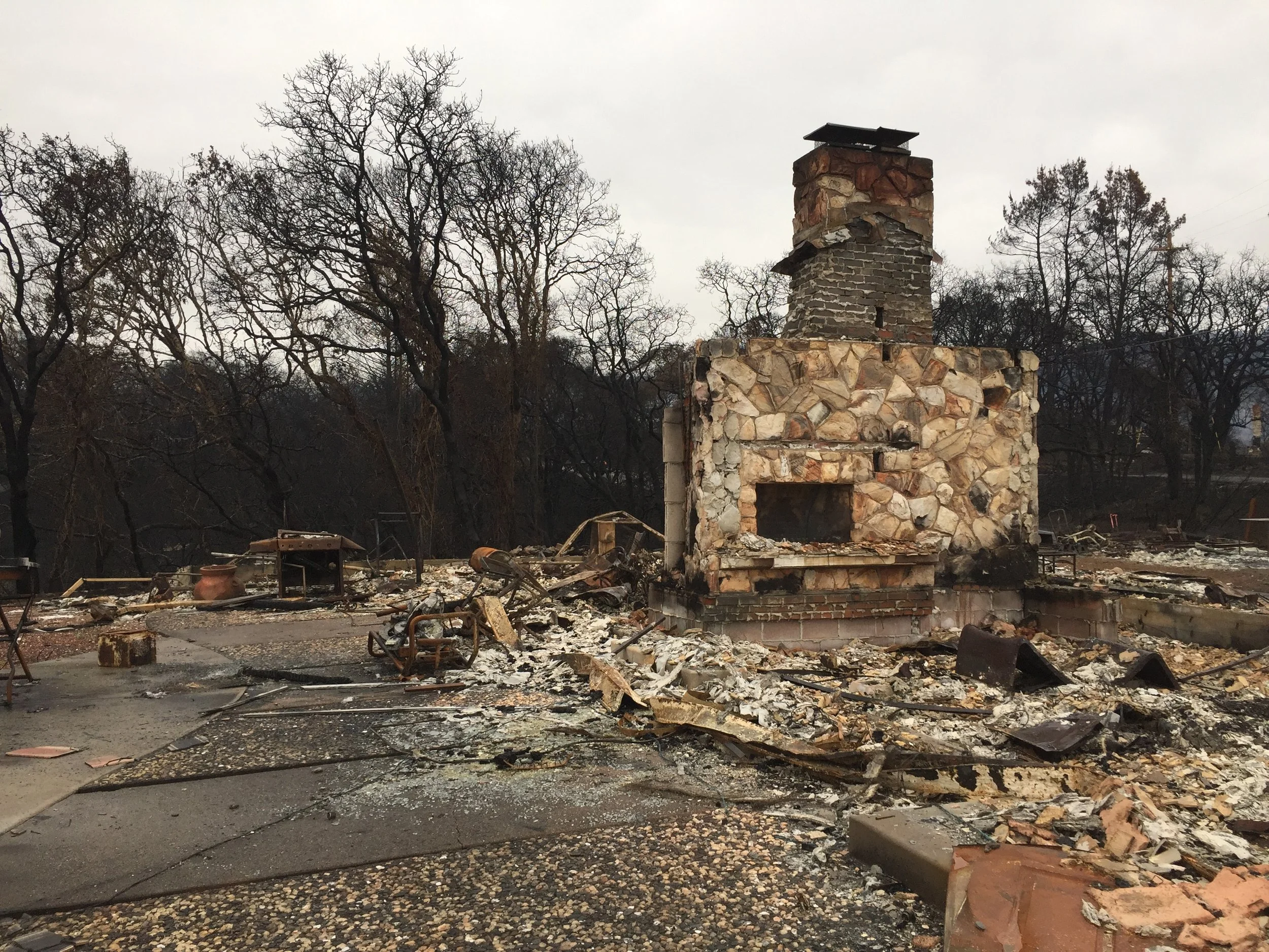
This case study provides information on the performance of a residential concrete foundation after adevastating fire in the city of Santa Rosa, California, USA. The fire started in the middle of night in mid-October 2017 and burnt nearly 8,000 residential and commercial structures. The majority of these structures were made with concrete foundation and timber or steel super structure. After the fire, only concrete foundations and masonry structures were still standing and rest of the structure was burnt to ground. Typical structures endured fire for about one hour with temperaturesthat reached up to about 1093°C (2000 °F). Since the fire spreadquickly and widely, the fire department could not effectively quench the fire with water, so the structures were allowed to burn. This residential foundation was about 400 square meters (4,000 sq. ft) in area. The concrete used was about 20 MPa (3,000 psi) in compressive strength and had primarily sandstone as aggregate.

Photograph 5: Overview of the concrete foundation after the debris was removed from the site.
Photograph 6: Verview of the structural damage to the concrete foundation after the the fire.
The condition evaluation consisted of field and laboratory testing. The field testing consisted of the following:
- Visual inspection & hammer sounding
- Nondestructive Rebound hammer test
- Nondestructive pulse velocity tests
- Uniaxial pull tests on anchor bolts
- Drilling cores through various parts of the foundation.
The laboratory testing consisted of:
- Core compressive strength test.
- Microscopic examination of concrete.
The summary of findings for the various tasks is as follows:
FIELD TESTING
Visual Inspection & Hammer Sounding
Photograph 6 shows the plan view of the house foundation. The visual observations showed that the foundation surface had various conditions ranging from no color change to pink, black, and whitish colors. The concrete stem walls had some spalls from debris clearing activity as well as from exposure to fire. The concrete foundation retaining walls in the garage area also showed some cracking in the pillars; however, the retaining walls showed minimal cracking. The driveway slab, patio slab, and entry were generally in good condition.
Coring
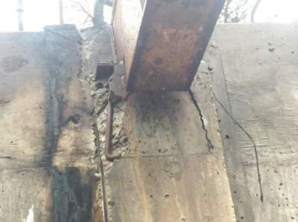
Nearly twenty, 100 mm (4-inch) diameter, cores were drilled through the foundation walls. Nine cores were drilled through the stem walls and one through the grade beam. Photograph7shows a typical core through the foundation wall affected by fire exposure.

Photograph 7: Core drilled from the concrete foundation wall that was charred from the fire exposure.
Non-Destructive Rebound Hammer
Testing The Rebound Hammer consists of a spring-controlled hammer mass that slides on a plunger within a tubular housing. When the plunger is pressed against the concrete surface, it reacts against the force of the spring; when completely retracted, the spring is automatically released. The hammer impacts against the concrete and the spring-controlled mass rebounds, taking the rider with it along a guide scale. The Rebound Hammer is principally a surface hardness tester with little apparent theoretical relationship between the strength of concrete and the rebound number recorded during the testing. The reading can be used to estimate the compressive strength of the concrete using the calibrated chart provided by the instrument manufacturer. Generally, several tests are conducted at each test locations and the readings are averaged. A better way to use the data is to check if the rebound numbers are generally similar. Similar rebound numbers indicate generally similar concrete quality and strength. The Rebound Hammer test readings at nearly 25 locations ranged from 30 to 37 with an average of 34. These rebound hammer test readings indicate a concrete compressive strength of approximately 21 to 31 MPa (3,000 to 4,500 psi). The rebound hammer readings were used primarily to obtain general information of concrete condition and strength, but not as an absolute value. It may be noted that the rebound hammer readings are dependent on concrete surface hardness and should not be considered an absolute value of strength for the inner concrete. The rebound hammer readings should always be calibrated against the actual concrete core strength.
Pulse Velocity Testing
In this method, a pair of piezoelectric sensors is placed at opposite ends of the test member. In one of the sensors, ultra sonic pulses are generated and the time it takes for the pulse to propagate through the concrete to the other sensor is measured by a control unit. Knowing the distance traveled, propagation velocity is calculated and based on the velocity, the internal flaws such as voids or significant cracking can be determined. The test was performed at a total of 10 locations. In general, the readings were repeatable and stable. Measured time of arrivals (TOA) for each 8-inch thick foundation wall are shown in the table. The data shows that the velocity in the stem wall varied between 2,870 m/s to 3,780 m/s (9,417 and 12,403 ft. per second) with an average of 3,454 m/s (11,334 ft/sec). The pulse velocity of 2,870 m/s (9,417 ft/sec) indicated a minor flaw - such as honeycomb or a crack - in the concrete. In general, the concrete test locations showed reasonably good velocity and no significant internal defect in the concrete foundation walls.
Anchor Bolt Pull-out Tests
A total of 20 bolts were tested for their pull-out strengths. Ten, 16 mm (5/8-inch) anchor bolts were tested in the house foundation. A total of 10 holdown anchor bolts were tested: five each in house foundation and in the garage foundation.
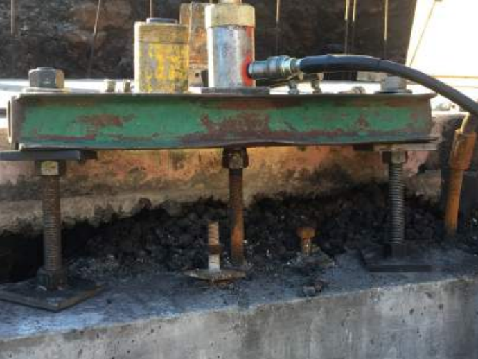
Photograph 8: Uniaxial pull test on anchor bolts to determine bond between concrete and steel.
The test criteria prescribed in the Sonoma County’s technical bulletin B43 was followed. Technical bulletin B43 prescribed following proof test loads. The proof test loads were applied for 10 seconds.
- lb ½-inch diameter (13 mm): 4,100
- lb 5/8-inch diameter (16 mm): 6,500
- lb ¾-inch diameter (19 mm): 9,600
- lb 7/8-inch diameter (22 mm): 13,300
The testing consisted of applying a uniaxial vertical load using a hydraulic jack withcalibrated equipment, and then holding the load for 10 seconds. If there was no drop in the load and the bolt did not slip, then the bolt was considered to have passed. Five out of ten16 mm(5/8-inch) diameter anchor bolts passed the test. Ten out of ten holdown bolts passed the test.
LABORATORY TESTS
Core Compressive Strength Tests A total of seven cores were tested by Signet Testing Laboratory, Hayward, CA, for the concrete compressive strength. The testing was performed in accordance with American Society for Testing & Materials ASTM C 42/39. The average compressive strength of six cores from the garage foundation was 27.8 MPa (4,030 psi). The average compressive strength of seven concrete cores from the house foundation was 26.5 MPa (3,840 psi) with strength variation within ten percentage indicating a good residual compressive strength and relatively uniform strength of concrete.
Microscopic Examination of Concrete
Cores A total of three cores were microscopically examined in accordance with ASTM C 856 primarily to determine the depth of fire damage to concrete. The microscopic examinations of cores showed fire damage up to a depth of 12 mm (½-inch)from the exposed surface.
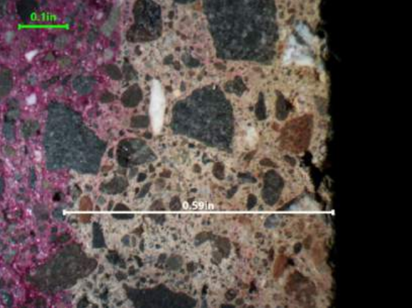
Photograph 9: Core showed that the carbonation was about 14.99
mm (0.59 inch) from the exterior surface. The phenolphthalein test
showed unchanged concrete color areas as carbonated whereas
the pink colored concrete is not carbonated. The outer 6.35 mm
(¼ inch)showed change in color of the cement paste due to fire
exposure. Some microcracks were observed in the fire affected
area, but no debonding was observed. Magnification 5x
The microscopic examinations showed that the concrete was normal weight concrete with aggregates primarily composed of 25.4 mm (1-inch) maximum size sub-rounded aggregate consisting of basalt/andesite and graywacke sandstone. The aggregate distribution and the concrete consolidation was good. The near surface concrete, within one inch from the exterior surface, had some micro cracks.
CONCLUSIONS
Based on the field and laboratory testing it was concluded that the residual concrete compressive strength was more than the typical foundation design strength of 17 MPa (2,500 psi). The footings and the grade beams below the soil line were unaffected and the fire damage to the concrete was less than 20 mm (¾-inch) from the fire exposed surface. The concrete to steel bond was determined to be good. It was decided that the foundation did not need complete removal, but neededreplacement of some sections and additional localized repairs to bring the foundation back to its pre-fire condition.

Ashok Kakade, P.E.
is a licensed professional civil engineer in the states of California, Nevada, and Arizona. He serves as a Principal Engineer with Concrete Science, Inc., located in Hayward, CA. With over 40 years of experience, he specializes in evaluating and repairing various concrete structures. Mr. Kakade is a Fellow of the American Society of Civil Engineers, the International Concrete Repair Institute, and the Indian Concrete Institute. He actively contributes to technical committees of the American Concrete Institute (ACI), International Concrete Repair Institute (ICRI), and the American Society for Testing & Materials (ASTM).